We recommend SpeakEasy in Seattle.


Try downloading some Animmusic!
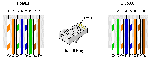
The pairs designated for 10BaseT Ethernet are orange and green. The other two pairs, brown and blue, are unused. The connections shown are specifically for an RJ45 plug. The wall jack may be wired in a different sequence because the wires may be crossed inside the jack. The jack should either come with a wiring diagram or at least designate pin numbers that you can match up to the color code below.

In order to make what is commonly referred to as a "Crossover" cable one must change the pinout connections on ONE end of the cable. If you do it on both ends of the cable you have crossed-over the crossover and now have a straight-through cable, albeit a very non-standard one. In this case two negatives do make a positive.
You need to make a cable where pins 1 & 2 from one end are connected to pins 3 & 6 on the other end, and pins 3 & 6 from the first end are connected to pins 1 & 2 on the other end. Pins 4 & 5 and 7 & 8 are unchanged.
The two ends look like this:

     Standard End                          Crossover End

       Pin 1 White/Orange                   Pin 1 White/Green

       Pin 2 Orange                         Pin 2 Green

       Pin 3 White/Green                    Pin 3 White/Orange

       Pin 4 Blue                           Pin 4 Blue

       Pin 5 White/Blue                     Pin 5 White/Blue

       Pin 6 Green                          Pin 6 Orange

       Pin 7 White/Brown                    Pin 7 White/Brown

       Pin 8 Brown                          Pin 8 Brown
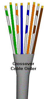
The following is the proper pin out and cable pair/color order for the
| Pair#2 is connected to pins 1 and 2 like this: | |
| Pin 1 wire color: | white/green |
| Pin 2 wire color: | green |
| Pair#3 is connected to pins 3 and 6 like this: | |
| Pin 3 wire color: | white/orange |
| Pin 6 wire color: | orange |

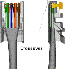
Then when the pairs are inserted into the RJ45 plug they should look like this:
